Working in Screen/Pixel Space
Pros
- 1 unit = 1 pixel, distance is easy to understand.
- Working with 2D sprites is straightforward.
- You can operate completely in whole numbers if you want to.
- A direct representation of what you see.
Cons
- The raster has no Z it is completely 2D.
- Y is going “down” instead of “up” unlike most mathematical Cartesian representations.
- Translating or rotating vector shapes using integers alone could cause significant errors and information loss.
- Everything is resolution dependent!
- Insufficient information available to represent a fully 3D environment.
Working in 3D Space
Pros
- A virtual 3D representation of all the things you “could” see!
- Full 3D Rotation, Translation and Scaling is possible without truncation errors!
- 1 unit = Whatever you want as long as you are consistent! (feet, meters, yards…)
- Independent of 2D raster resolution!
Cons
- Not as direct when working in 2D alone.
- Requires Rasterization: The conversion of vector coordinates to raster coordinates so shapes can actually be drawn.
- More complex to understand.
The Screen in 3D Normalized Device Coordinates
A.K.A The Canonical View Volume.
This coordinate system is always the same regardless of what you set your screen pixel width & height.
Notice how the origin is now in the center and that we have a Z axis available.
As we start to work in 3D this system will be much easier to deal with.
Using 3D to Our Advantage
- We will learn many ways to take advantage of this new system.
- To start we will need a better way to represent a location in this space.
- A “Vertex” representing where two edges meet will be very convenient.
- Coding Tip: struct VERTEX { float xyzw[4]; uint color; }
- We won’t really capitalize on the Z or W today, but they will be useful later…
- Once our shapes are stored in this 3D Space, it will be easier for us to rotate them around the screen center. (now the origin)
Adding Flexibility: Shaders
- Currently if you draw a line… you draw EXACTLY that line…
- Wouldn't it be useful to draw the same line in a different spot without having to remake it? What if we wanted to do this every frame?
- What if multiple lines needed to move or rotate together as a group?
- What if we wanted to temporarily draw the line a different color?
- Perhaps our vector “spaceship” takes some damage and should flash red!
- Shaders are customizable and “interchangeable” functions that intercept & modify data right before we draw it to the screen.
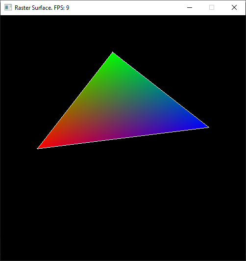
Triangle Rasterization
- The last type of primitive we will learn to draw on the 2D raster grid is going to be the triangle.
- However, we will define them in our new 3D coordinate system.
- Triangles can be connected together to form every other type of polygon, which makes them very versatile.
- Nearly everything you see in a modern game or simulation is comprised of triangles.
- Your current knowledge would allow you to draw the “outline” of a triangle, but not much else.
- In order to “fill” a triangle with pixels, we will need to dig deeper into the math behind triangles, and how the space within a triangle is defined.
Barycentric Coordinates
Defines a Non-Orthogonal coordinate system describing the space of a triangle.
Any position on this plane can be described with the following equation:
P = β( B – A ) + γ( C – A ) + A
Terms Reordered:
P = ( 1 - β - γ )A + β( B ) + γ( C )
α = ( 1 - β - γ )
P ( α, β, γ ) = αA + βB + γC
Finding the Barycentric Coordinates of a point relative to a triangle
β = ImplicitLineEquation ( B, line AC )
γ = ImplicitLineEquation ( C, line BA )
α = ImplicitLineEquation ( A, line CB )
b = ImplicitLineEquation ( P, line AC )
y = ImplicitLineEquation ( P, line BA )
a = ImplicitLineEquation ( P, line CB )
Pβγα = ( b / β , y / γ, a / α )
Could we use the Barycentric coordinates to detect if we are inside or outside the triangle? If so… how?
Brute Triangle
FOR ALL PIXELS
bya = FindBarycentric ( CurrX, CurrY )
IF b >=0 && b <= 1 &&
y >=0 && y <= 1 &&
a >=0 && a <= 1
THEN
PlotPixel ( CurrX, CurrY )
Better Brute Triangle
StartX = MIN ( X1, X2, X3 )
StartY = MIN ( Y1, Y2, Y3 )
EndX = MAX ( X1, X2, X3 )
EndY = MAX ( Y1, Y2, Y3 )
FOR StartY to EndY
FOR StartX to EndX
bya = FindBarycentric ( CurrX, CurrY )
IF b >=0 && b <= 1 &&
y >=0 && y <= 1 &&
a >=0 && a <= 1
THEN
PlotPixel ( CurrX, CurrY )
Lari’s Parametric Triangle
- Step 1: Sort the VERTS in Y Ascending.
- Step 2: Determine the “Direction of Fill” by comparing the Middle vertex to the opposite line. (Use the Implicit Line Equation)
- Step 3: Use the Parametric Line Equation to find the closest staring pixel for each row on the tallest line. (Top to Bottom)
- Step 4: Determine if the Pixel’s center is within the Barycentric space of the triangle. If it is you should Draw that pixel.
- Step 5: Continue drawing pixels on that row until you leave Barycentric space. (Ignore any pixels below the parametric line)
Barycentric Interpolation
- Surprise! Barycentric coordinates are ALREADY ratios that add up to 1
- Linear Interpolation: X = ( B – A ) * R + A
- Linear written another way: X = ( B * R ) + A * ( 1 – R )
- 1.0 = β + γ + α So…
- Barycentric Interpolation: X = A * α + B * β + C * γ
- Well that was easy! =)